
Updating…
-
-
- No products in the cart.
Subtotal: 35,80 € (incl. VAT)
Subtotal: 35,80 € (incl. VAT)
The FX Teacher methology
Or how to build a working kit every time!
the infallible method fx teacher
Since 2013, I have been doing a lot of prototypes! And I am sharing this experience with collaborators, trainees, musicians…
Unfortunately, I see the same mistakes every time! The most frequent one for my Padawans…. They want to rush!
As soon as we receive the PCB, they get excited and go for it! 2h later they plug it in, play some chords and….. Well, it doesn’t work!
the principle
The methodology has 3 goals :
To do so, our team breaks down how they work.
Then we’re going to explain step by step what you need to measure and what you need to see.
If a value doesn’t correspond, you’ll know where it comes from.
Then you can easily describe you problem to the FX Teacher community, or even debugging by yourself. Just read the schematic again and surf through the internet with the terms related to your problem.
in specific terms
Assemble the tester
The kit to make the tester is available on our store
To build your FX Teacher tester, here are the tools you’ll need :
You will also need to prepare your cables and jacks. Stripping and bending them has already been explained in this article.
power supply input
what does it serve
Without energy, the circuit will never work!
It is moreover the most ridiculous mistake but also the easier to spot. “Erm… It doesn’t work!”, “You didn’t plug the power supply you piece of cake!”
Well you understood well, we’re going to start with the power supply bloc for each of our kits!
By the way, this jack has 2 duties. The first one is to provide the circuit with energy for any 9V power supply. The second one is to easily allow you measuring your current consumption. It is made so you don’t have to solder and desolder cables, thanks to its claws. Maybe it’s not very striking. But believe me, it’s a huge gain of time!
How to assemble it
We’re gonna start by soldering the female jack connector, in which you plug you power supply. As electrolytic capacitor work, the long leg is (+) and the short one is (-). By convention we’re gonna connect the red cable to (+) and the black one to (-). Cables are between 8 and 10cm.
No need to heat a lot, it is easily and quickly soldered. Moreover the pin inserts are made of plastic, so we better not damage them.
Now we’re going to cut 4 pieces of heat shrink tube that we’re going to put on the jack side.
We continue by clamping the other side of the cable with the crocodile clips
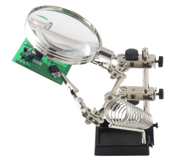
Here we’re going to heat things up! The contact surface is wider, do not hesitate to heat and wait a bit to pour the tin. You’ll see, once the clip is at the good temperature, the tin will spread. Thus using a third hand holder is a good idea to avoid burning your table.
We wait till it’s cold. Then we overlay the weldings with the heat shrink tube pieces. Finally, we have to heat with the upper part of the soldering iron (the opposite part of the tip) or a lighter. If you have a hot air station it’s even better!
But wait! You have a cable and 2 crocodile clips remaining!
Solder one crocodile clip on one side
Wait till it’s cold
Add 2 pieces of heat shrink tube on the side you just soldered.
Solder the other crocodile clip
Finish by shrinking the tubes.
We’re going to use this clip to measure currents with desoldering everything!
How to use it
The power supply bloc is the first one we’re going to assemble! To do so, follow the instructions on your tutorial and you should have something similar :
You can then solder the black cable and the red one on your board. They will always be mounted on your board from start to finish.
Now plug your power supply for effect pedals on your kit. Use the clips to connect the red clip to the red cable and conversely. There’s very little risk to make a mistake here!
You know what? It’s done! Your circuit is power supplied.
Now you can to the multimeter section to understand how to read voltages and currents. You’ll then be able to compare your findings with the given table provided in your kit.
audio jacks
what does it serve
The main goal is to be able to easily listen with a guitar and an amp or with a sound card, the outcome!
So we’re going to to plug those jacks on each bloc of our kit and analyze its impact on the signal.
How to assemble it
Let’s begin by identifying the functional anatomy of a stereo female jack :
First we have to solder a white cable to the tip connector of the jack. Then a black one the ground connector.
Just repeat for the output jack with a green cable.
Cable lenght, approximately 10cm.
Cut 2 small pieces of heat shrink tube and put them on the jack side.
Now solder the other crocodile clip. Be careful to tighlty clamp the clip on the wire with the nose plier
Time to heat things up again! The metallic surface is wide, so you have to heat the clip, and when it’s hot enough the tin will start spreading easily and it will be shiny.
With the upper part of your soldering iron (the lowest temperature-wise) or a lighter, shrink the tubes on the exposed metallic parts.
Just do the same for the output jack tester with the green cable instead of the white one.
How to use
As you noticed it, they’re jacks. So you can easily plug an input and ouptut jack, and listen to the result.
When you’re board will be finished, you should have one white cable, one green, and two black ones. Just catch them with the crocodile clips and you can appreciate the outcome. Even without a housing!
The FX Teacher methodology is the same idea. When you’re first bloc is finished, we exactly tell you where to place your wire to inject your guitar signal and analyze the bloc impact on your computer.
So it would be convenient and easier for you not to break your tester or your PCB in the long run, we decided to solder cables on those points.
Once the cables are soldered, you just have to connect them with your clips.
Now, to analyze your signal you must plug your sound card! Nothing special, plug the output jack of your sound card to the input of your PCB. Then the PCB output jack to the sound card input.
It’s up to you to follow-up the tutorial about Audacity, to understand how to analyze your signal.
bench switching!
You can wrap up the soldering iron, now we’re moving on to the measurements!
use a multimeter
I know you’re going to love it!
When protoyping, the multimeter is a must have…
So we’re going to see together how do to the different measurements so you can easily compare your circuit to the reference table.
voltmeter
theory
This is the easiest unit to measure, just plug yourself in parallel connection! Which means that the circuit works normally and that the voltmeter comes “from above” to check the signal. So you get a measurement in Volts, V. Actually it’s a potential difference. A potential which is different on the voltmeter pins. That means that whenever you’re making a voltage measurement, to get one pin on the circuit where you want to make your measure, and the other on ground!
connection
amperemeter
theory
Compared to voltages, currents are measured in serial connection! Indeed, you have to be able to know the amount of electrons rushing into and out the circuit. To do so, we’ll take the main entrance, the red cable!
Then your multimeter will do the job counting the electrons per second!
connection
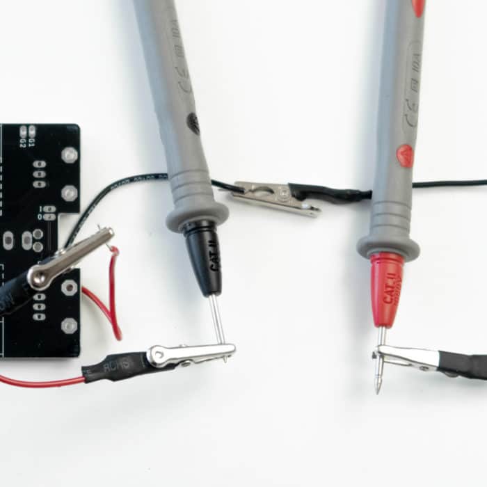
The two-headed crocodile clip will be useful here, connect it between the red cable off your PCB, to the red clip of your DC jack tester.
photo sur la carte
continuity
The continuity test should help solve a lot of your problems!
It’s about resistivity measurement. But here, the multimeter will bleep
when the the resistor value is 0. Which means that both potentials are on the same point! There are only 2 situations in which this potentials are 0. First option is when the developper purposely link to areas together on the PCB. The second option is when you do bad welding that creates a bridge between 2 pads!
So we often use this method to check every area of the board by bleeping risky areas. It allow us to know where the issue comes from.
You build your board bloc by bloc, so it will be super fast to go through the PCB!
However, this methodology only works if you know how to read a schematic and a PCB on Eagle. You’re not obliged to use it on our kits to debug them, but it’s better to learn it at least.
photo de la carte en test avec un pont et la r à 0. Meme sans le pont.
Power supply load
We’re often taught at school a perfect power supply gives a nice 9v, and that’s it! That’s completely false. The power supply always has an output impedance, depending on design and performance.
It’s only a few hundreds mOhms but you’ll see it affeccts its performances.
Without a doubt you heard about the Ohm’s law. U = R* I. Voltage = resistance * current.
So if you draw 1A in the circuit, with an output impedance of 0.1Ohms, you’ll lose 0.1V.
Actually it’s no big deal in this situation. But sometimes other impedances add themselves to the power supply signal path. So you might find yourself at the end of your path with a few tens of Ohms!
On the other hand, we lose a lot of voltage if the current is high.
You’re lucky, on never top 200mA in effect pedals with semiconductor. Just remember that with 10Ohms, it is 2V of loss!
Thus by building your board bloc by bloc, you’re going to make measurements of a power supply which is not sending any current!
So we’re going to build step by step and then come back to check everything once in load.
You’ll see that some voltages might change, others might not.
So it’s a double check for mistakes like ripping a cable, or creating a bridge over pads.
sound card measurements
The sound card is a wonderful tool that is not only useful for recording demos! We’re going to discover what we can do with a simple but efficient software like Audacity.
Bases of signal processing
Before getting into manipulations, some reminders on signal processing. Or teaching for some of you. I’d advice you to go check the subject in depth if you’re interested because we’re going to approach it quickly! And it is wonderful to me, as a musician.
signal amplitude
You saw previously that we can measure the voltage of a signal in Volts, thanks to a multimeter. In a sound card your signal can’t top a maximal value depending on the model. Let’s imagine 5V. If you send a signal bigger than 5V, it’s going to clip, adding a lot of harmonics that don’t sound great.
Thus the dBFS unit was born, for decibel full scale.
If you send a 5V signal in this sound card, it is 0 dBFS.
If you send a 2.5V signal, it is -3dBFS. While dividing by 2 an amplitude, is equivalent to losing 3dBs.
So it is interesting for recordings to work between -6dBFS and -3 dBFS. But if you’re recording an OD and you crank up the gain, you might go to +9 to +15dB. You would exceed the 0dBFS so there would be saturation. And then we come back to the clipping problem… A clipping sound card does not sound as good as a clipping OD!
Therefore, we chose -12dBFS to optimize this gap that might get analyzed. Or we chose -3DBFS and we start recording once the pedal volume control is set.
snr
Why don’t we simply choose -20dBFS?
Because of the SNR! Signal Noise Ratio.
The noise floor of system is often between -60 and -100dBFS. If you”re signal is around -10dBFS, your SNR is 100-10 = 90 dB in the best case.
You must keep an excellent SNR if you want good measurements.
So we can’t send a -20dBFS signal if the noise floor is -60dBFS. You might lose a lot of useful informations harmonic-wise!
time signal
To represent these analysies, you have a temporal and frequential representation of your signal.
Time signal is exactly what you would be measuring with your multimeter if it was precise and fast enough. Then you would note step by step its time evolution. So this measure is purely physical.
the tff
In contrast the TFF is a signal we invented to analyze the signal in a better way.
Here’s the formula, you might like it :
What you must understand is that the TFF is a signal calculated from the time signal. And we don’t show the amplitude as a function of time, but as a function of its frequency!
Common stimulis
the spectrogram
To do a TFF, you choose a sample of your time signal and you calculate it frequential content. Now imagine a filter that changes with time!
To analyze this kind of signla, we invented the spectrogram!
The software is going to make a TFF on a lot of samples of your signal in real time, then you’ll have a 3D representation of your signal.
The signal evolves in time on the X axis, frequencies are shown on the Y axis and finally the color shows on Z axis the power in the frequencies.
We mostly use it to see how the filter act according to time on different riffs or to adjust precisely a filter.
This is often what you see when scientists analyze singers vocal chords.
What you most know about Audacity
So here we go to do a visit of the Audacity software. I will show you everything you must know to follow our tutorials.
Set the audio peripherials
Before starting your project you must check that you’re sound card is configured the right way. To do so, check you chosed it for input and output. And not the intern device of your computer
No need to choose 96kHz for sampling. Any card working with 44.1kHz, 24 bits will do. Afterward if your sound card allows it, you can go higher with this parameter.
generate signals
Record a signal, mute, solo
Once your signal is generated, you ‘ll have to send it to your circuit board and record at the same time. So you must change the software parameters to be able to read and record at the same time.
Once you’re done, the first recording is simple. Plug everything in and hit the red button to record. If everything’s fine, it’s recording, then you stop when you want.
Be careful when tracks get piled up. Keep in mind to hit the SOLO button to avoid sending multiple signals at the same time!
set sound card and signal level
We’re going to use the Vu meter at the top of the window for this step.
Before measuring, you must calibrate your sound card.
Plug in a jack between the input and the output of your sound card to make a bypass.
Send a long 1kHz sinus, for a few minutes, with an amplitude of -12dBfs and record at the same.
No adjust the input potentiometer of your sound card so the input level is exactly the same as the output one.
Imprim ecran -12dB output et input
do a tff
Generate a signal or use a recording.
Then go to Analyze -> Draw spectrum
About windowing
The window will affect your analyze. You must have some theorical knowledges to set it nicely. We know a sinus a only one ray. So we’re going to be more likely to take the right window. We will need to adapt ourselves because no windowing fits every need!
In our case, Blackman-Harris was more strict but so much more precise that we barely see the ray at 997Hz.
The next step is the point number. The more you have points, the it is defined! But sometimes we are more likely to use less points to get a smooth result which is necessary sometimes.
We have much more details that does not confirm theory and are useless for our study.
Last point but not least, the scale on the frequency axis. It can be linear, which means the gap between 100 and 200Hz is the same as between 200Hz and 300Hz.
It can also be logarithmic, which is actually how our ears work. Here the gap between 100 and 200Hz is wider than between 200Hz and 300Hz. It’s a little bit more complex than that so here’s the formula if you want to learn more.
As you can see, on the right we’ll have much more informations on what goes around 1kHz. And this is between 100Hz and 6kHz that most of our guitar signal is!
Display a spectrogram
Here, nothing’s easier! Go to the signal you want to analyze. Regarding the present case, it is shown in a temporal format. Clic on the small arrow on the top right corner. A lot of options apppear, and sepctrogram is part of them!
Common mistakes
Ask us your questions! As they come we’ll take time to reference them here.
4 replies to “The FX Teacher methology”
Michel Perez
Bonjour à l’équipe, je viens de recevoir mon kit ego drivers avec le 3pdt (sans pcb au passage normal?)
J’ai certes une connexion lente ici mais je ne trouve pas de schéma d’implantation, ce que vous expliquez est cool pour des novices mais dans cet ensemble d’informations je ne trouve pas cette information un peu nécessaire ! par ailleurs je suis luthier (dans un genre atypique et si j’ai commandé c’est pour tester votre produit et éventuellement l’insérer dans une série d’instruments ( basse ou guitare de voyage) le moment venu il serait bon de se connaitre et de discuter un peu
Merci pour vos liens et bonne continuation Musicalement M Pérez
alexandre ernandez
Bonjour Michel,
Merci pour votre achat et votre 1er kit FX Teacher 🙂
Je vois sur votre commande que vous n’avez pas pris le kit complet mais uniquement le kit électronique et un 3PDT seul.
Si vous souhaitez un kit true bypass complet, voici un lien : https://anasounds.com/fr/produit/kit-true-bypass-3pdt/
Vous aurez ainsi le PCB qui complète le 3PDT.
Pour les schémas d’implantation tout est sur la page dédiée à l’Ego Driver : https://anasounds.com/fr/assembler-son-ego-driver/
Bon build ! Et n’hésitez pas à nous envoyer des photos de vos créations 🙂
PL
Bonjour,
on voit sur les images que vous n’utilisez/fournissez pas de composant de surface (surface-mount), est-ce un choix par rapport à la qualité du son ou un autre critère que vous pouvez expliquer, est-ce le cas aussi pour les pédales qui ne sont pas en kit ?
Merci de votre réponse et longue vie à votre beau travail !
PL
Loick Jouaud
Bonjour,
Toutes nos pédales actuelles sont en traversant, tout simplement car c’est le plus simple en terme de fabrication à la main. Le CMS demande des machines supplémentaires pour pouvoir produire plus rapidement que le traversant. Sinon niveau son, les 2 technologies sont équivalentes.
Bonne journée !