
Updating…
-
- No products in the cart.
Subtotal: 15,90 € (incl. VAT)
Subtotal: 15,90 € (incl. VAT)
read a bom and fill your pcb
In this article I will tell you how to read a Bill Of Materials (BOM), identify your kits components and how to correctly place them on your Printed Circuit Board (PCB).
Before going any further, we’re going to get some reminders on
PCBs, BOM, and every piece of equipment you need to work well. If you’re already familiar with this stuff, you can skip the explanation and go to the tutorial part by clicking here.
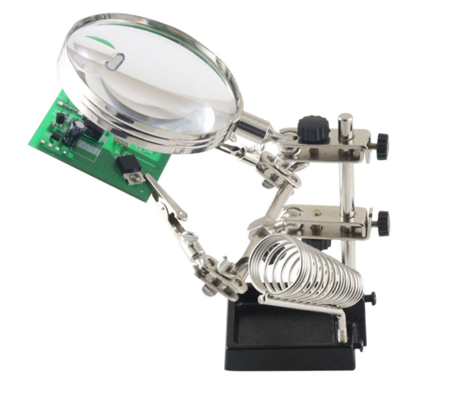
what you need on your bench
recommended tools
Here’s a list of tools you’re gonna need. You don’t have to get all of these tools in particular but it would help a lot.
my favourites
classics
documents and equipment you need before you start
technical information
This is a reminder on some interesting notions. You can skip it and move directly to the assembling.
the pcb (printed circuit board)
If the pedal is the body, the PCB is the heart! It contains all the connections to give life to the schematic
how do we make a pcb
Most of PCBs are made in Asia, you just have to be specific to get what you want. For your own prototypes, I’d advice you to go to PCB Way. It is more than enough if you build PCBs from time to time.
Our PCBs are made from a FR4 plate (some sort of plastic fiber). On each side, the manufacturer adds a copper layer. Then only our routings, that we make with a software, are kept in the copper layer. Afterwards a milling machine drills the plate, and a surface treatment metallizes the holes. The plate is then coated with a thin gold layer that protects the whole card from corrosion. Finally, instructions are drawn in a white writing to indicate component placements, board serial number, etc…
how to make your own pcb
You may have guessed, to make a PCB, you absolutely need a good technical drawing. That’s what we call a typon, and we get it using a CAD software.
Our team works with Eagle PCB, the interface is user-friendly and there are a lot of available librairies.
Then, when we discover new sounds in the R&D department; we go onto this sofwtare, draw the schematic, and make the routing.
Indeed, The schematic is a visual and very simple to understand form. Anyone can understand it very quickly and it’s a necessary step before making the PCB. We can also transfer the schematic to another software and simulate how it works.
the bom (bill of materials)
Once we receive the PCBs, all we have to do is to export the BOM from the software. It is actually a list containing all the components that must be on the board. We know what to choose, what it is, and where to solder!
I’ll explain to you how to read it :
mounting of the electronic components
In this part you’re gonna discover how to mount each of the components on your board! At the same time I’ll tell you how where they come from, how to identify them and why we use them.
resistors
color code method
Whenever you have a pedal, you have resistors. They resist to the current flow in a circuit (hence their name). And if you learn a bit more about electronics, you’ll learn that you can do much more functions !
To identify a resistor value, given in Ohms (Ω), manufacturers agreed on a common color code. This color code is made thanks to color rings on the resistor, which translate into values.
For your information, we relieve mathematical writings such as :
To give you a order of magnitude, values betwenn 1Ω and 1kΩ are considered small. Between 100kΩ et 2.2MΩ is considered super large!
multimeter method
You want to go easy ? Switch on your mulitmeter on Ohmeter mode and read their value thanks to the probes!
okay then, but why ?
When you’ll get your FX Teacher kit delivered, you’ll have a bag with different value resistors mixed. You’ll eventually need to know which one is the 10kΩ resistor to put on R4!
2 Options :
how to mount them on board
why this kind of resistor and not another one?
There are dozens of different resistor types and manufacturers ! While some still like carbon resistor for their vintageness, they are not very precise and they are noisy. So we trusted the brand Xicon with their metal film resistors.
They offer a much more precise value, with a 1% error rate. And, a thermic sensibility of 50ppm which is ridiculous. We chose a line with a power handling of 1/4W, which is more than enough for pedal manufacturing.
With this line I’m sure not to alter the quality of my electronic design! This is why we trust them for the production of our Anasounds pedals for years.
capacitors
operating principle
capacitor physics
A capacitor is made of 2 metallic plates separated by an insulator. When we apply a voltage on its terminals, the 2 electrodes get positively loaded on one side, and negatively loaded on the other one. Once we release this voltage, both poles are going to discharge energy in the circuit. Considering their value, this amount will be released quicker or slower.
A current is generated in the circuit depending on the formula i(t) = C * d u(t)/dt.
i is the current injected in the circuit. C is the capacity of the capacitor. u is the voltage on the capacitor terminals.
the types of capacitors
The first domain of improvement focused on by scientists was the insulator. We don’t use any capacitor for any situation! So we selected 3 technologies for differents uses, ceramic, film et electrolytic.
Some capacitors are polarized which means that they have to be mounted respecting a + and a -. And others are not, meaning that how you place them doesn’t matter.
One last thing to remember about capacitors, all of them have a specific charge voltage ! It means that we furnish you capacitors with a charge capacity of 25V and 50V depending on their types. It is more than enough pedalwise. But be careful, don’t try to mount one of this caps on the power supply stage of an amp. It will litteraly blow to your face! It’s déjà vu…
Also something loved by “vintage” manufacturing, caps with 250V charge voltage for a guitar signal… It will be the opposite, using voltages between 20mV and 18V. Good luck exploiting it to its full potential . The cap will just age faster.
our capacitors lines
sensibility
p = pico = 10^(-12) = 0.000 000 000 001
n = nano = 10^(-9) = 0.000 000 001
µ = micro = 10^(-6) = 0.000 001
m = milli = 10^(-3) = 0.001
F = Farads, unit used to represent the capacity C of a capacitor
ceramic
Ceramic Capacitor are not polarized ! So we can mount the way we want . Leur valeur est toujours en pF.
For values, there are 3 numbers on the capacitor. First 2 indicate its value. Third one indicate its power of ten.
Here are a few examples :
Once you know its value, you just have to mount the capacitor.
As usual,read the BOM, identify the value and find the name on the PCB. Then place it and fold the legs outwards.
Now you just have to solder!
film
read film capacitor value
Film capacitor are not polarized either! You can connect it either way.
The value indicated on it is whether given in µF or nF.
Thus, we mark it all as nF on the BOM except for 1µF. It avoids writting 1000nF, which is mathematical heresy!
I might suck out some of your brain cells witht his part.
Once you know how to read one, you can chill for the rest of your life!
mount a fil cap on the PCB
How to do it, as said it is not polarized so there is no reverse. Then push it in and fold the legs outwards. What remains is soldering!
We use this wonderful line of capacitor because they do not produce any harmonic distortion! It is unfortunately quite differetnt from ceramic capacitor . That’s why we would rather use film capacitor for filtering.
When we go above µF we have to switch to electrolytic caps. This is the challenge of our R&D team to stay between 1nF and 1µF on filtering.
electrolytic
read electrolytic capacitor value
So they are the only polarized capacitor we used!
Once we have read its value, we have to discover where are + and –
terminals to place them!
To read its value, this is super easy! They are pretty big, so everything you need to know about them is written on ! Moreover, All electrolityc capacitor have values in µF So no doubt allowed about it.
if you read 47 or 47µF, it’s 47µF !
However be careful not to confuse the capacitor value with its operating voltage! Most of the time 25V, 50V and 100V.
mount electrolytic capacitor
To find the “-” terminal, there are 2 approaches:
Footprint of the E2 electrolytic capacitor on the PCB, with its “+” symbol
On the PCB, we always indicate the “+” terminal, inside or outside the cercle. Just know that the “-” is on the other side. It’s in the bag!
We chose Nichicon because one of their line is dedicated to audio applications! Very low ESR (equivalent serial resistance) , so definitely something we don’t want!
Finally, It has a life expectancy of at least 2000 hours at least in load.
These characteristics are over average and the price/u stays coherent for effect pedals
the semiconductors
theory and evolution
Semiconductors are part of the active components family!
Resistors and capacitors are passive components awaiting for a signal and energy to interact with the sound.
Active components are power supplied and can by themselves generate a signal or amplificate it.
In the first half of the XXe century, the diodes apperared. Then after WW2, silicum and germanium diodes come to the market! By assembling 2 PN
junctions (diodes), we discovered the transistor in 1947. It was a true revolution, because the transistor can amplify a signal the same way lamps do ! (they apparead in 1919). The first transistor radios were born in 1954. Then come in 1958 the printed circuit boards with the first op-amps! It’s a set of miniature transistors integrated in a chipset that can achieve a lot of functions and operations!
This innovation led to the creation of microcontrollers, microprocessors that are composed of even more transistors, billions, always smaller and more efficient…
This is the domain I grew up in. When I worked at NXP Semiconducteurs, we were developping integrated circuits in the audio technologies.
diodes
recognize them
To know a diode value, you must read each letter around its surface. This value starts in 80% of cases by “1N”. Only a few diodes like the 1N34A don’t have their name written on it. Thus, we have to identify them with practice…
place a diode on the pcb
Once we have the value, we have to be carefgul, there is direction on the diode and it is very important! the ring drawn on the diode shows the cathode, the “-“, it is also drawn on the PCB. Then you have to mount it with the stripes of diode and of the PCB on the same side.
In pedals, we find diodes for various fucntions :
transistors
identify transistors
To begin with, there’s a lot more room on a transistor to write things!
On the flat face is written the value (Most of time starts with 2N or BC). The round face is used a mark. This curves are also drawn on the PCB to identify where to put which side.
Transitors are made of 3 electrodes. Regarding the transistor itself, they have different functions and different connections. (If you want to learn more, search “YOUR TRANSISTOR REF” then “PINOUT”). But in our case, there is no need to do it!
mount a transistor on a pcb
Plug the transistor, fold the legs and solder, once more, that’s all you have to do!
In our circuits, most of the time we use transistors to amplify a signal or to adapt impedances. Look the buffer from this article. And we’ll talk about it later in future articles.
intergrated circuits (op-amps and others)
We can read its value directly on the top of the IC. NE555, TL072 etc… Remember to solder the socket first, then plug the chipset on it.
Warning, IC need to be placed with a specific direction! Each leg is very important and does rigorously different thing! So make sure to mount the socket first. Whether a stripe or a dot for the ICs, and a notch for the socket and the PCB.
On the left, a TC1044 which is a power supply chip, drawn rawly with its 8 legs
In the middle, we have an op-amp, another type of IC we use a lot. It’s easier to draw in various smaller parts on the schematic.
On the right is a part of an op-amp, these are the 2 legs connected to the power supply.
Op-amps are very nice amplifierswith which we can do a lot of things! High quality filters, give gain to the saturation stage, etc…
It’s a primordial component to all of our designs! We’ll talk about it more in depth later too.
trimpots
identify the trimpots
Trimpots are nothing more that miniature potentiometer on PCB ! They allow us to offer thin adjustments and to add settings.
On the pic, the left trimpot is shown in top view. There is a screwdriver print with 2 half-circles. It shows us the cursor of the trimpot. Here it is halfway of its total range.
The right one shows the value indication. It’s quite like ceramic capacitors, P103 for 103. 103 being 10 x 10^3 or 10kOhms.
Yes trimpots unit is “Ohms” just like resistors, simply because they are variable resistors!
mount a trimpot on a pcb
Once placed, as usual, fold the legs outwards,flip, and solder !
Common values :
103 = 10kOhms
203 = 20kOhms
503 = 50k Ohms
104 = 100kOhms
105 = 1MOhms
terminal block
We’re going to see them a lot with FX teacher ! On one hand it is soldered on the PCB thanks to its legs. On the other, we connect the new component we want thanks to the hubs. To do so just screw it to connect it to the circuit!
It’s great tool for learning and audio discovery that we cherish at Anasounds!
Of course, be careful to place it in the right direction. So you can easily access the hubs to put component legs.
We left some free room around them to manipulate and let the components breath.
did you like this entry?
Do you want us to do more? Support this project and subscribe now!
1 replies to “read a bom and fill your pcb”
Olivier
Merci pour ce partage d’informations !
Thanks for sharing your knowledge !